
1 General Description
The EM78F651N is an 8-bit microprocessor designed and developed with low-power, high-speed CMOS technology
and high noise immunity. It has an on-chip 1K×13-bit Electrical Flash Memory and 128×8-bit in system programmable
EEPROM. It provides three protection bits to prevent intrusion of user’s Flash memory code. Twelve Code option bits
are also available to meet user’s requirements.
With its enhanced Flash-ROM feature, the EM78F651N provides a convenient way of developing and verifying user’s
programs. Moreover, this Flash-ROM device offers the advantages of easy and effective program updates, using
development and programming tools. User can avail of the ELAN Writer to easily program his development code.
2 Features
CPU configuration
• 1K×13 bits on-chip ROM
• 80×8 bits on chip registers (SRAM)
• 128 bytes in-system programmable
EEPROM
*Endurance: 100,000 write/erase cycles
• More than 10 years data retention
• 5-level stacks for subroutine nesting
• Less than 2 mA at 5V/4MHz
• Typically 20 μA, at 3V/32kHz
• Typically 2 μA, during sleep mode
I/O port configuration
• 2 bidirectional I/O ports
• Wake-up port : P6
• High sink port : P6
• 8 Programmable pull-down I/O pins
• 8 programmable pull-high I/O pins
• 8 programmable open-drain I/O pins
• External interrupt : P60
Operating voltage range:
• Operating voltage:
2.4V~5.5V at -40°C ~85°C (Industrial)
• Operating voltage: 2.2V~5.5V at 0°C ~70°C
(Commercial)
Operating frequency range (base on two clocks):
• Crystal mode:
DC ~ 16 MHz @ 5V
DC ~ 8 MHz @ 3V
DC ~ 4 MHz @ 2.2V
• ERC mode:
DC ~ 16 MHz @ 5V
DC ~ 8 MHz @ 3V
DC ~ 4 MHz @ 2.2V
• IRC mode:
DC ~ 12 MHz @ 4.5V~5.5V
DC ~ 4 MHz @ 2.2V~5.5V
All the four main frequencies can be trimmed by
programming with five calibrated bits in the
ICE652N Simulator. Flash is auto trimmed by
ELAN FWriter.
Three available interrupts:
• TCC overflow interrupt
• Input-port status changed interrupt (wake-up from
sleep mode
• External interrupt
Fast set-up time requires only 2ms in high Crystal and
32 CLKS in IRC mode from wake up to operating mode
Peripheral configuration
• 8-bit real time clock/counter (TCC) with selective
signal sources, trigger edges, and overflow
interrupt
• Power down (Sleep) mode
*Vdd power monitor and supports low voltage detector interrupt flag • 4 programmable Level Voltage Detector (LVD)
• Three security registers to prevent intrusion of
Flash memory codes
• One configuration register to accommodate user’s
requirements
• 2/4/8/16 clocks per instruction cycle selected by
code option
• High EFT immunity
Single instruction cycle commands
Four Crystal range in Oscillator Mode
Crystal Range Oscillator Mode
16 MHz ~ 6 MHz HXT
6 MHz ~ 1 MHz XT
1 MHz ~ 100kHz LXT1
32.768kHz LXT2
Programmable free running watchdog timer
Package type:
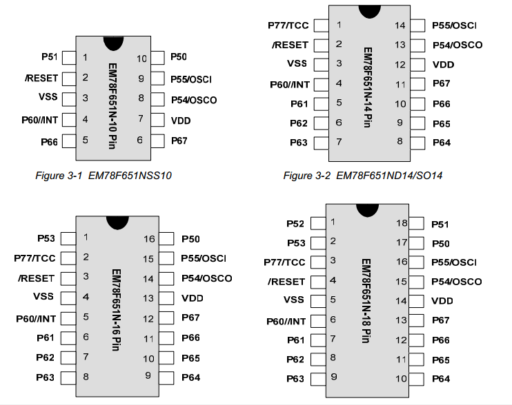
• 10-pin SSOP 150mil : EM78F651NSS10J/S
• 14-pin DIP 300mil : EM78F651ND14J/S
• 14-pin SOP 150mil : EM78F651NSO14J/S
• 16-pin DIP 300mil : EM78F651ND16J/S
• 16-pin SOP 150mil : EM78F651NSO16AJ/S
• 18-pin DIP 300 mil : EM78F651ND18J/S
• 18-pin SOP 300mil : EM78F651NSO18J/S
• 20-pin DIP 300mil : EM78F651ND20J/S
• 20-pin DIP 300mil : EM78F651NSO20J/S
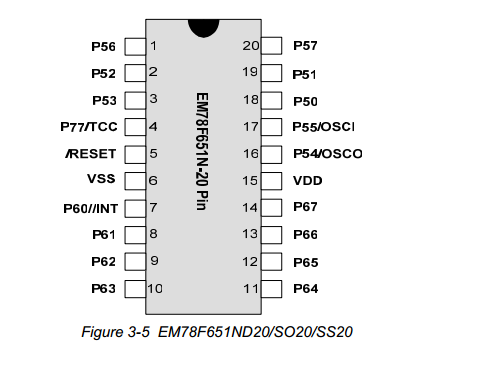
• 20-pin SSOP 209mil : EM78F651NSS20J/S
Green products do not contain hazardous substances